ISO/IEC 10918-1 : 1993(E)
B.2.3
Scan header syntax
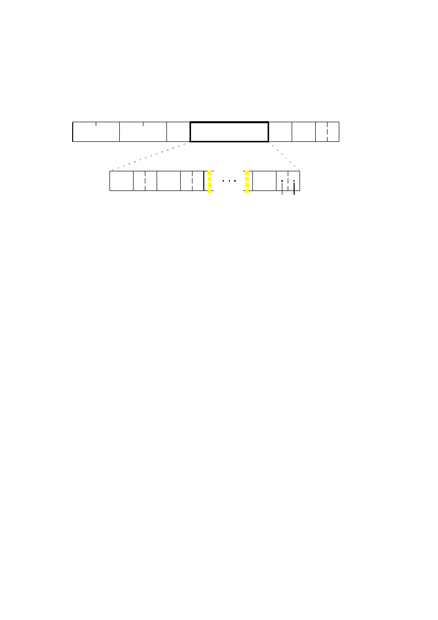
Figure B.4 specifies the scan header which shall be present at the start of a scan. This header specifies which
component(s) are contained in the scan, specifies the destinations from which the entropy tables to be used with each
component are retrieved, and (for the progressive DCT) which part of the DCT quantized coefficient data is contained in
the scan. For lossless processes the scan parameters specify the predictor and the point transform.
NOTE If there is only one image component present in a scan, that component is, by definition, non-interleaved. If there is
more than one image component present in a scan, the components present are, by definition, interleaved.
2
2
2
Ns
Td
Ns
Ta
Ns
Cs
SOS
Ls
Ns
Ss
Se
Ah
Al
Cs
1
Td
1
Ta
1
Cs
Td Ta
TISO0860-93/d022
Scan header
Component-specification
parameters
Scan component-specification parameters
Figure B.4 Scan header syntax
Figure B.4 [D22], = 5.5 cm = 215.%
The marker and parameters shown in Figure B.4 are defined below. The size and allowed values of each parameter are
given in Table B.3.
SOS:
Start of scan marker Marks the beginning of the scan parameters.
Ls:
Scan header length Specifies the length of the scan header shown in Figure B.4 (see B.1.1.4).
Ns:
Number of image components in scan Specifies the number of source image components in the scan. The
value of Ns shall be equal to the number of sets of scan component specification parameters (Cs
j
, Td
j
, and Ta
j
)
present in the scan header.
Cs
j
:
Scan component selector Selects which of the Nf image components specified in the frame parameters
shall be the jth component in the scan. Each Cs
j
shall match one of the C
i
values specified in the frame header,
and the ordering in the scan header shall follow the ordering in the frame header. If Ns > 1, the order of
interleaved components in the MCU is Cs
1
first, Cs
2
second, etc. If Ns > 1, the following restriction shall be
placed on the image components contained in the scan:
j
N
j
j
s
H
V
=
×
1
10,
where H
j
and V
j
are the horizontal and vertical sampling factors for scan component j. These sampling factors
are specified in the frame header for component i, where i is the frame component specification index for which
frame component identifier C
i
matches scan component selector Cs
j
.
As an example, consider an image having 3 components with maximum dimensions of 512 lines and
512 samples per line, and with the following sampling factors:
Component
Component 1
Component 2
2
0
4
1
1
2
2
2
0
0
1
1
2
H
V
H
V
H
V
=
=
=
=
=
=
,
,
Then the summation of H
j
×
V
j
is (4
×
1)
+
(1
×
2)
+
(2
×
2) = 10.
The value of Cs
j
shall be different from the values of Cs
1
to Cs
j 1
.
CCITT Rec. T.81 (1992 E)
37