background image
ISO/IEC 10918-1 : 1993(E)
The baseline sequential process uses Huffman coding, while the extended DCT-based and lossless processes may use
either Huffman or arithmetic coding.
4.7
Sample precision
For DCT-based processes, two alternative sample precisions are specified: either 8 bits or 12 bits per sample. Applications
which use samples with other precisions can use either 8-bit or 12-bit precision by shifting their source image samples
appropriately. The baseline process uses only 8-bit precision. DCT-based implementations which handle 12-bit source
image samples are likely to need greater computational resources than those which handle only
8-bit source images. Consequently in this Specification separate normative requirements are defined for 8-bit and
12-bit DCT-based processes.
For lossless processes the sample precision is specified to be from 2 to 16 bits.
4.8
Multiple-component control
Subclauses 4.3 and 4.4 give an overview of one major part of the encoding and decoding processes ­ those which operate
on the sample values in order to achieve compression. There is another major part as well ­ the procedures which control
the order in which the image data from multiple components are processed to create the compressed data, and which
ensure that the proper set of table data is applied to the proper data units in the image. (A data unit is a sample for lossless
processes and an 8
×
8 block of samples for DCT-based processes.)
4.8.1
Interleaving multiple components
Figure 11 shows an example of how an encoding process selects between multiple source image components as well as
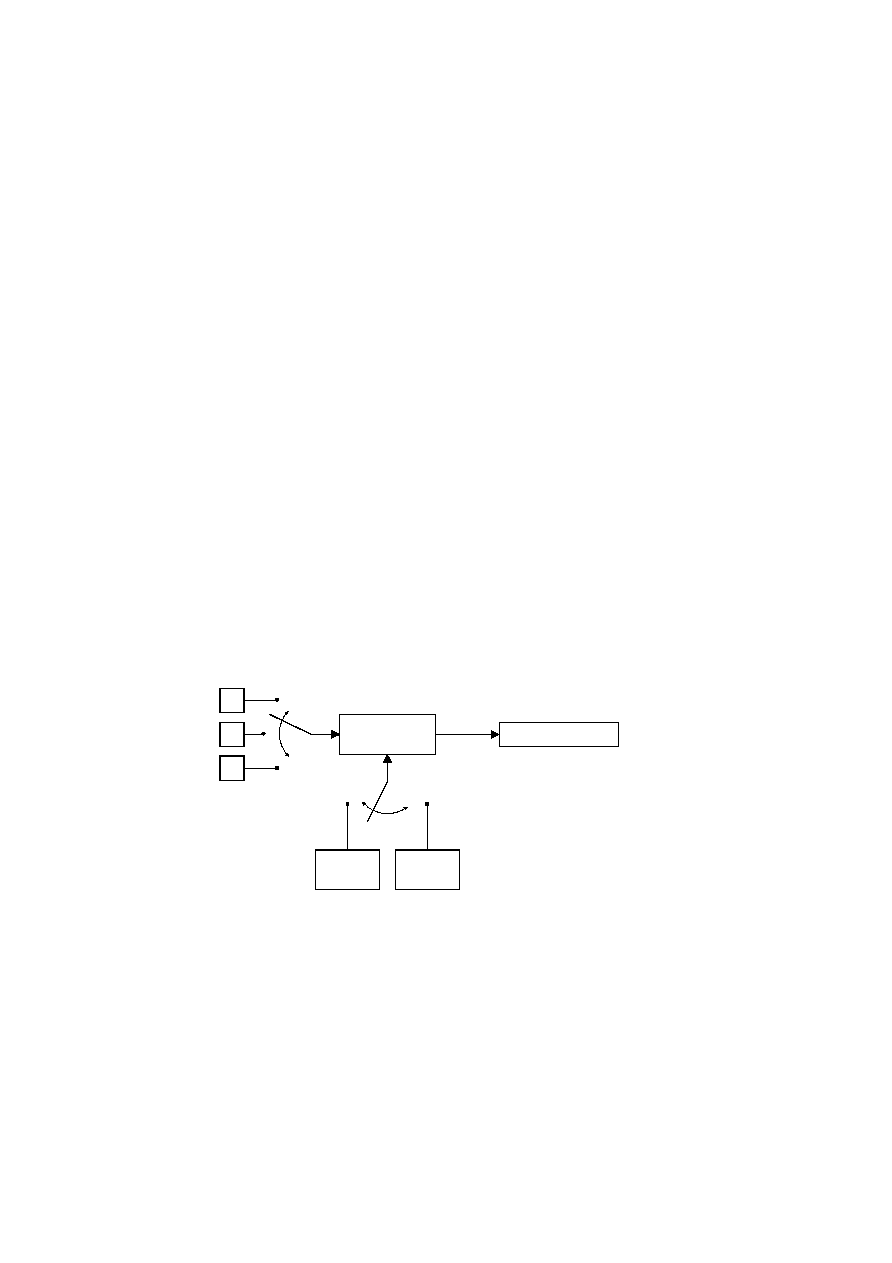
multiple sets of table data, when performing its encoding procedures. The source image in this example consists of the
three components A, B and C, and there are two sets of table specifications. (This simplified view does not distinguish
between the quantization tables and entropy coding tables.)
TISO0750-93/d011
A
B
C
Encoding
process
Source
image data
Table speci-
fication 1
Table speci-
fication 2
Compressed
image data
Figure 11 ­ Component-interleave and table-switching control
FIGURE 11 [D11] 7 cm = 273 %
In sequential mode, encoding is non-interleaved if the encoder compresses all image data units in component A before
beginning component B, and then in turn all of B before C. Encoding is interleaved if the encoder compresses a data unit
from A, a data unit from B, a data unit from C, then back to A, etc. These alternatives are illustrated in Figure 12, which
shows a case in which all three image components have identical dimensions: X columns by Y lines, for a total of n data
units each.
CCITT Rec. T.81 (1992 E)
19
[1] [2] [3] [4] [5] [6] [7] [8] [9] [10] [11] [12] [13] [14] [15] [16] [17] [18] [19] [20] [21] [22] [23] [24] [25] [26] [27] [28] [29] [30] [31] [32] [33] [34] [35] [36] [37] [38] [39] [40] [41] [42] [43] [44] [45] [46] [47] [48] [49] [50] [51] [52] [53] [54] [55] [56] [57] [58] [59] [60] [61] [62] [63] [64] [65] [66] [67] [68] [69] [70] [71] [72] [73] [74] [75] [76] [77] [78] [79] [80] [81] [82] [83] [84] [85] [86] [87] [88] [89] [90] [91] [92] [93] [94] [95] [96] [97] [98] [99] [100] [101] [102] [103] [104] [105] [106] [107] [108] [109] [110] [111] [112] [113] [114] [115] [116] [117] [118] [119] [120] [121] [122] [123] [124] [125] [126] [127] [128] [129] [130] [131] [132] [133] [134] [135] [136] [137] [138] [139] [140] [141] [142] [143] [144] [145] [146] [147] [148] [149] [150] [151] [152] [153] [154] [155] [156] [157] [158] [159] [160] [161] [162] [163] [164] [165] [166] [167] [168] [169] [170] [171] [172] [173] [174] [175] [176] [177] [178] [179] [180] [181] [182] [183] [184] [185] [186]