ISO/IEC 10918-1 : 1993(E)
SOF
3
:
Lossless (sequential), Huffman coding
SOF
9
:
Extended sequential DCT, arithmetic coding
SOF
10
:
Progressive DCT, arithmetic coding
SOF
11
:
Lossless (sequential), arithmetic coding
Lf:
Frame header length Specifies the length of the frame header shown in Figure B.3 (see B.1.1.4).
P:
Sample precision Specifies the precision in bits for the samples of the components in the frame.
Y:
Number of lines Specifies the maximum number of lines in the source image. This shall be equal to the
number of lines in the component with the maximum number of vertical samples (see A.1.1). Value 0 indicates
that the number of lines shall be defined by the DNL marker and parameters at the end of the first scan (see
B.2.5).
X:
Number of samples per line Specifies the maximum number of samples per line in the source image. This
shall be equal to the number of samples per line in the component with the maximum number of horizontal
samples (see A.1.1).
Nf:
Number of image components in frame Specifies the number of source image components in the frame.
The value of Nf shall be equal to the number of sets of frame component specification parameters (C
i
, H
i
, V
i
,
and Tq
i
) present in the frame header.
C
i
:
Component identifier Assigns a unique label to the ith component in the sequence of frame component
specification parameters. These values shall be used in the scan headers to identify the components in the scan.
The value of C
i
shall be different from the values of C
1
through C
i
-
1
.
H
i
:
Horizontal sampling factor Specifies the relationship between the component horizontal dimension
and maximum image dimension X (see A.1.1); also specifies the number of horizontal data units of component
C
i
in each MCU, when more than one component is encoded in a scan.
V
i
:
Vertical sampling factor Specifies the relationship between the component vertical dimension and
maximum image dimension Y (see A.1.1); also specifies the number of vertical data units of component C
i
in
each MCU, when more than one component is encoded in a scan.
Tq
i
:
Quantization table destination selector Specifies one of four possible quantization table destinations
from which the quantization table to use for dequantization of DCT coefficients of component C
i
is retrieved. If
the decoding process uses the dequantization procedure, this table shall have been installed in this destination
by the time the decoder is ready to decode the scan(s) containing component C
i
. The destination shall not be re-
specified, or its contents changed, until all scans containing C
i
have been completed.
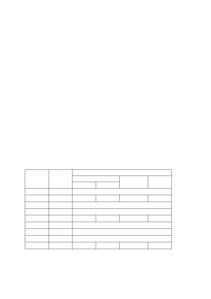
Table B.2 Frame header parameter sizes and values
Values
Parameter
Size (bits)
Sequential DCT
Progressive DCT
Lossless
Baseline
Extended
Lf
16
8
+
3
×
Nf
P
1
8
8
-255
8, 12
8, 12
2-16
5
Y
16
0-65 535
X
16
1-65 535
Nf
1
8
1-255
1-255
1-4
1-255
C
i
1
8
0-255
35
H
i
1
4
1-4
3550
V
i
1
4
1-4
3550
Tq
i
1
8
0-3
12
0-3
55
0-3
0
-125
36
CCITT Rec. T.81 (1992 E)